What Is an Induction Motor and How Does It Work?
An Induction Motor converts electrical energy into mechanical motion without direct electrical connections to its rotor. It powers pumps, conveyors, compressors, fans, and machine tools. In many factories, its steady hum marks the rhythm of daily production.
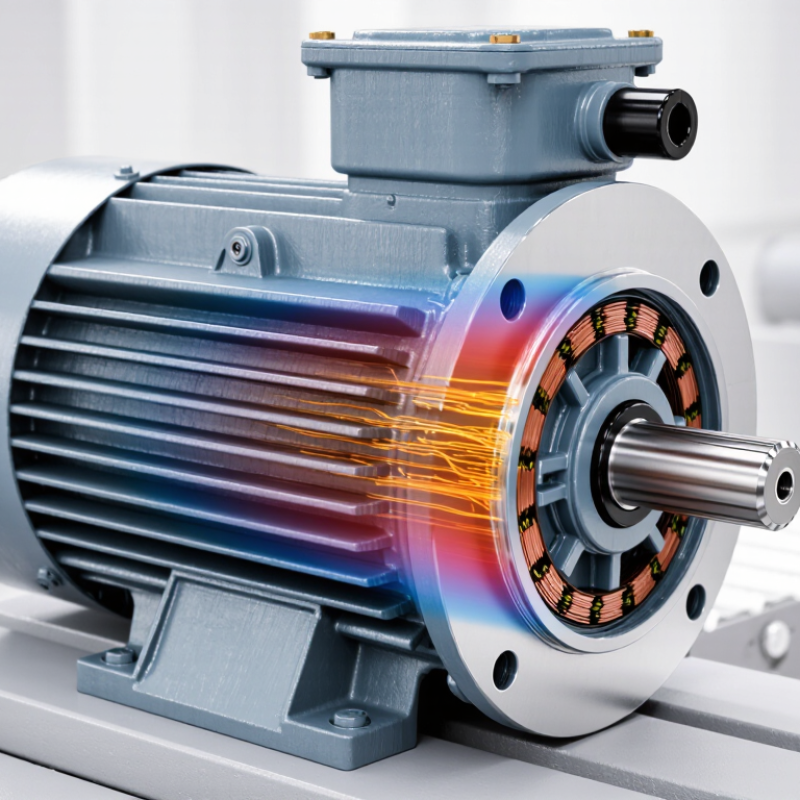
Stephen J. Chapman, author of Electric Machinery Fundamentals, calls it “the workhorse of industry.” That description remains practical. An Induction Motor is rugged, affordable, and relatively simple to maintain. Its stator receives alternating current and creates a rotating magnetic field. This field crosses the air gap and induces current in the rotor. The rotor then develops torque and begins to turn.
The process sounds simple. It is not always simple.
A small speed difference must exist. This difference is called slip. Without slip, the rotor would not experience changing magnetic flux, and torque would disappear. A squirrel-cage rotor uses conductive bars joined by end rings. There are no brushes to replace. That design improves durability, especially in dusty industrial rooms.
Yet efficiency depends on details. Poor alignment, overloaded bearings, voltage imbalance, and blocked cooling passages can shorten service life. A motor may still run while quietly losing performance. That is where practical inspection matters. Technicians check temperature, vibration, current, insulation, and unusual noise. These observations often reveal problems before failure becomes obvious.
This article explains what an Induction Motor is and how it works. It follows the energy path from the stator windings to the rotating shaft. It also examines slip, torque, motor types, efficiency, and common operating limits. Some explanations simplify the physics. That is a weakness worth remembering. Real motors behave differently under changing loads, temperatures, and supply conditions.
Definition and Basic Purpose of an Induction Motor
An induction motor is an electric machine that converts electrical energy into rotary motion. Its basic purpose is practical: it drives pumps, fans, compressors, conveyors, and many industrial machines.
Unlike a brushed motor, it does not need direct electrical contact with the rotating part. Alternating current creates a rotating magnetic field in the stator. This field induces current in the rotor, producing torque and movement.
The rotor turns slightly slower than the magnetic field. This difference is called slip, and it is essential for torque production. Without slip, no current would be induced in the rotor.
The idea sounds simple. Real machines are less perfect. Friction, heat, voltage imbalance, and changing loads reduce efficiency. In a workshop, a lightly loaded motor may sound smooth but still waste energy through fixed losses.
These figures explain why the induction motor remains important. Its rugged construction, moderate cost, and limited maintenance suit demanding equipment. A motor connected to a pump, for example, can run for thousands of hours while its magnetic field transfers energy without brushes.
However, nameplate efficiency does not guarantee efficient operation. Oversizing, poor alignment, or frequent starts can undermine expected performance. Engineers should measure load, temperature, vibration, and power factor instead of trusting assumptions.
FAQS
An induction motor converts electrical energy into rotary motion through electromagnetic induction. It normally needs no direct rotor connection.
Alternating current flows through insulated windings in the stator. These windings create a rotating magnetic field, like an invisible carousel.
Changing magnetic flux passes through the rotor bars. This process induces current without direct electrical contact.
Slip is the speed difference between the magnetic field and the rotor. The rotor must turn slightly slower. Without slip, torque disappears.
The shaft carries torque to equipment such as pumps, fans, or conveyors. Bearings support the shaft and reduce friction. The frame holds everything firmly.
A small air gap separates the stator and rotor. An uneven gap can increase vibration, noise, and energy waste. That small space matters.
A cooling fan moves air across the housing. It helps remove heat from windings and bearings. Dust can reduce cooling performance.
They check vibration, temperature, insulation, current, and unusual noise. A hot bearing may suggest misalignment, poor lubrication, or excessive load.
No. A clean-looking motor can still contain a developing problem. Sound alone may mislead. Measurements provide stronger evidence, although interpretation is not always perfect.
Conclusion
An Induction Motor is an electrical machine that converts alternating electrical energy into mechanical motion without requiring a direct electrical connection to its rotating part. Its main components include a stationary stator with windings, a rotating rotor, an air gap, a shaft, bearings, and a protective frame. The stator creates a rotating magnetic field, while the rotor receives induced current through electromagnetic induction. The interaction between the magnetic field and the rotor current produces torque, causing the rotor to turn.
During operation, alternating current enters the stator windings and generates a rotating magnetic field. This field moves slightly faster than the rotor, inducing voltage and current in the rotor conductors. The resulting magnetic interaction accelerates the rotor and drives the connected load. Common types include squirrel-cage and wound-rotor motors. They are widely used in pumps, fans, compressors, conveyors, machine tools, household equipment, and many industrial systems because of their reliable construction, simple operation, and relatively low maintenance needs.