Choosing the right Synchronous Motor in 2026 requires more than comparing rated power and purchase price. Modern facilities expect high efficiency, stable speed, lower maintenance, and dependable operation under changing loads. The correct choice must fit the complete application, not just the nameplate.
Nikola Tesla, whose alternating-current motor research shaped modern electrical engineering, wrote, “The motor is the inverse of the dynamo.” That idea remains useful today. A motor converts electrical energy into controlled mechanical work, but its real performance depends on system details. These include load torque, starting conditions, operating speed, power factor, ambient temperature, and drive compatibility.
Small details matter.
A pump may need steady torque for long operating hours. A compressor may demand strong starting performance. A conveyor can experience sudden load changes and frequent stops. These situations may require different rotor designs, excitation methods, cooling systems, or variable-frequency drives. Selecting only by horsepower can create poor efficiency, difficult commissioning, or unexpected downtime.
This guide examines the practical decisions behind a reliable Synchronous Motor selection in 2026. It considers permanent-magnet and wound-field designs, efficiency classes, control requirements, maintenance access, and lifecycle cost. It also questions common assumptions. The most efficient motor on paper may not be the best choice in a dusty plant or a weak electrical network. That is where judgment matters.
Specifications can be incomplete.
Engineers should verify test conditions, thermal limits, protection ratings, and supplier support before approving a final design. Experiences from real installations often reveal issues that catalog tables overlook.
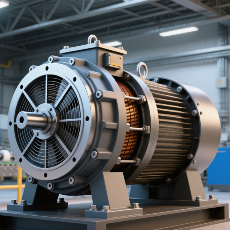
How to Choose the Right Synchronous Motor in 2026?
Define Load, Speed, Torque, and Duty Using IEC 60034-2-1 Test Data
Start with the driven equipment, not the motor catalogue. Record the continuous load, peak torque, required speed, and operating hours. A conveyor carrying wet material may need more starting torque than its steady running load suggests. For synchronous speed, check the supply frequency and motor pole count. Then confirm that the selected motor can handle the actual load profile.
IEC 60034-2-1 provides standardized methods for determining motor losses and efficiency. Use the test report to check whether reported results match your intended operating conditions. Rated-point efficiency alone may not describe frequent starts, partial-load operation, or changing torque. That difference matters.
Tips: Ask for the test conditions, measured losses, and efficiency data. Compare them with your expected duty cycle, not just the nameplate rating.
Check the duty classification and thermal limits against real operating patterns. Include starts per hour, acceleration time, ambient temperature, and any periods of overload. A motor that meets the speed and torque targets may still run too hot under repeated starts. I would leave room for uncertainty: field loads rarely behave as neatly as a spreadsheet. Verify assumptions with site measurements or a documented engineering review before final selection.
Choosing between permanent-magnet, reluctance, and wound-field synchronous motors means looking beyond the IE4 or IE5 label. Permanent-magnet motors can deliver high efficiency and strong torque in a compact frame, especially with variable-speed control. Yet magnet temperature limits and material costs deserve attention. Reluctance motors avoid magnets and can suit demanding duty cycles, but their performance depends heavily on rotor design and drive settings. Noise and torque ripple may matter on a quiet production floor. Small details count.
Wound-field motors let operators adjust excitation, which can help across changing loads and power-factor requirements. Their excitation system adds components, losses, and maintenance considerations. An IE5 claim is not a complete comparison: check the applicable standard, rated power, speed, cooling method, and whether the motor is assessed with its converter. Ask for test data at the operating points your equipment actually uses. A pump running near full load differs from a conveyor that starts often. Estimates can still miss real-world heat, harmonics, or part-load hours; measure where possible. Choose the motor whose verified efficiency and service needs match the duty, not simply the highest class on paper.
Choosing a synchronous motor starts with the supply it will actually receive. Record the available voltage, frequency, phase, and expected load before comparing nameplates. A 400 V, 50 Hz supply is not interchangeable with a 460 V, 60 Hz system. Even when a motor can tolerate both, its speed, torque, and thermal limits may change. Small mismatches matter.
Use IEC 60034-30-1 to check the motor’s efficiency classification, but confirm that the standard’s scope and edition fit the motor type and application. An IE class describes efficiency under defined conditions; it does not certify every operating point or control arrangement. Ask for test data and rated values, then compare them with the duty cycle. Check whether the motor is intended for direct-on-line operation or converter supply. Do not assume the label settles that question.
Controls need equal attention. A variable-speed drive must suit the motor’s voltage, current, frequency range, and control method. Review low-speed cooling, starting torque, and any excitation requirements with the supplier. On site, compare the proposed settings with measured supply conditions and the driven machine’s load profile. That sounds simple. It isn’t. Specifications can leave gaps, and the neatest selection spreadsheet may miss a hot enclosure or frequent starts. Record those uncertainties before purchase.
Choosing a synchronous motor starts with the real operating cycle, not just the nameplate kilowatts. S1 describes continuous operation at a steady load; S2 covers short-time operation followed by a cooling interval. S3 and S4 account for intermittent running, with S4 also including frequent starts. Later duty types address braking or changing speeds and loads. Details matter.
Record load, run time, rest time, starts per hour, and driven-equipment inertia. A conveyor that runs steadily may fit S1, while a compressor that starts repeatedly can create extra rotor and stator heating. Use the duty description to assess thermal capacity, then check ambient temperature, altitude, cooling method, and allowable temperature rise. A short peak load is not automatically safe. The cooling interval must be real.
Treat S1–S9 as IEC duty designations, not as NEMA MG 1 categories. For a NEMA-based specification, verify the applicable MG 1 requirements for temperature rise, insulation, service factor, and operating conditions; limits depend on motor design and rating. Do not assume a service factor makes every overload acceptable. Compare the actual cycle against the manufacturer’s thermal data, and ask for clarification when duty details are incomplete. I have seen one overlooked restart assumption change the sizing decision. That part deserves a second look.
Use the duty classification that matches the complete operating cycle—not just the motor’s average output power. The ratings below summarize IEC 60034-1 duty types; actual thermal capacity depends on the motor design, cooling method, ambient conditions, starts, load profile, and applicable standard requirements.
| Duty type | Operating pattern | Thermal sizing considerations | Useful application data | Typical example |
|---|---|---|---|---|
| S1 — Continuous duty | Constant load for long enough to reach thermal equilibrium. | Select for continuous rated output at the actual ambient temperature, altitude, voltage, frequency, and cooling conditions. | Continuous kW or torque, speed, ambient temperature, altitude, cooling arrangement, and load margin. | A continuously operated process compressor. |
| S2 — Short-time duty | Constant load for a specified short period, followed by a rest period long enough for the motor to return close to ambient temperature. | Check the specified operating duration and cooling interval. Do not treat a short-time rating as a continuous rating. | Load, operating time per run, rest time, number of runs, and starting frequency. | An actuator that runs briefly and remains idle between operations. |
| S3 — Intermittent periodic duty | Repeated cycles of constant load and rest; starting does not significantly affect motor heating. | Assess cyclic heating and cooling. The cyclic duration factor is operating time divided by total cycle time, expressed as a percentage. | Load, on-time, rest time, cycle duration, and cyclic duration factor (ED). | A periodically operated indexing or positioning drive with modest starting impact. |
| S4 — Intermittent periodic duty with starting | Repeated cycles include starting, operation at load, and rest; starting materially affects heating. | Include starting losses and acceleration duty in the thermal assessment. Verify the permitted starts and starting time for the selected motor and load inertia. | Starts per hour, load and speed profile, acceleration time, driven-load inertia, and rest duration. | A frequently started conveyor or hoist drive. |
| S5 — Intermittent periodic duty with electric braking | Repeated cycles include starting, operation at load, electric braking, and rest. | Account for both starting and braking losses, braking method, cycle frequency, and thermal effects of the complete cycle. | Starts and braking events per hour, braking time, speed, inertia, load, and cooling intervals. | A cyclic drive requiring frequent controlled deceleration. |
| S6 — Continuous-operation periodic duty | Repeated cycles alternate between load and no-load operation, without a rest period. | The motor remains energized and operating during no-load intervals, so those intervals are not equivalent to a cooling rest period. | Loaded and no-load durations, cycle time, speed, and load level. | A machine that alternates between cutting and no-load running. |
| S7 — Continuous-operation periodic duty with starting and braking | Repeated cycles include starting, operation at load, and electric braking, without a rest period. | Evaluate cumulative heating from repeated starts and braking; do not assume a cooling interval between cycles. | Cycle time, starts and braking events per hour, load, speed, inertia, and braking method. | A continuously cycling drive with frequent reversals or stops. |
| S8 — Continuous operation with periodic load and speed changes | Repeated cycles operate at different combinations of load and speed, without a rest period. | Check heating at each load-speed combination and the cooling available at each speed. For a synchronous motor, confirm that the selected control method supports the required speed changes. | Load and speed at each step, time at each step, number of cycles, and ventilation performance. | A process drive that runs at several defined operating speeds and loads. |
| S9 — Non-periodic duty with load and speed variations | Load and speed vary non-periodically; the duty may include frequent overloads. | Use the measured or specified load-time profile. Check peak torque, overload duration, starts, speed range, and worst-case thermal conditions; average power alone is insufficient. | Time-series load and speed data, overload magnitude and duration, acceleration events, and cooling conditions. | A variable process drive with irregular production loads. |
| Check | What to verify | Selection implication |
|---|---|---|
| Applicable NEMA MG 1 requirements | Confirm the MG 1 edition and the sections applicable to the motor type, rating, construction, and intended service. | Do not apply one generic limit to every synchronous motor; requirements depend on the applicable rating and construction. |
| Voltage and frequency | Check the nameplate rating, supply tolerance, frequency, and the applicable MG 1 provisions. Commonly cited MG 1 guidance for many motor ratings addresses voltage variation of ±10% at rated frequency and frequency variation of ±5% at rated voltage; confirm applicability and any combined-variation conditions in the governing edition. | Supply variation can affect current, torque, speed behavior, and temperature. Do not use a tolerance statement as a substitute for confirming the actual operating point. |
| Temperature rise and insulation | Verify the specified temperature-rise method and limit, insulation system, ambient conditions, and any service factor or rating assumptions stated for the selected motor. | A duty designation by itself does not establish a permissible temperature rise or guarantee a particular thermal margin. |
| Starting and pull-in performance | Check starting method, load inertia, acceleration time, pull-in torque, synchronization requirements, and allowed starts for the specific motor and drive system. | The motor must both accelerate the load and synchronize successfully without exceeding its thermal or mechanical limits. |
| Cooling, enclosure, and installation | Confirm cooling method, enclosure, ventilation, mounting, ambient temperature, altitude, and site conditions against the motor’s rated data. | Reduced cooling or harsher site conditions can require a derating or a different motor configuration. |
| Variable-speed operation | If a drive is used, verify the motor’s suitability for the drive waveform and speed range, plus low-speed cooling and insulation considerations. | A standard constant-speed rating may not represent allowable output over the full variable-speed operating range. |
Practical sizing rule: document the complete load-time-speed cycle, calculate or obtain the motor manufacturer’s thermal assessment for that cycle, then confirm starting, synchronization, cooling, and applicable NEMA MG 1 requirements. S10 is an additional IEC duty type and is not included here because this table is limited to S1–S9.
How to Choose the Right Synchronous Motor in 2026?
Evaluate Lifecycle Cost, Payback, and Energy Savings Under ISO 50001 Metrics
A motor’s purchase price is only one part of its cost. Compare installation, electricity, maintenance, and expected downtime over its service life. Use actual operating hours and load data where possible. A motor running near full load for long shifts may justify a higher initial investment through lower energy use. Measure before buying. If the load varies, avoid assuming the motor will always operate at its rated point.
For an ISO 50001-aligned assessment, establish an energy baseline and track relevant energy performance indicators, such as kilowatt-hours per unit produced. Compare the proposed motor with the existing system under similar production conditions. Estimate annual savings, then calculate simple payback by dividing the added investment by annual net savings. Include maintenance differences, and test the result against changing energy prices or operating hours. These estimates are useful, but they are not guarantees; real production rarely stays perfectly steady.
Tips: Record motor hours, load, and energy use before selecting a replacement. Check that the comparison reflects the driven equipment, controls, and actual duty cycle. Keep the assumptions visible, especially when data is incomplete. A small measurement gap can change the payback.
Record continuous load, peak torque, required speed, operating hours, and starts per hour. Include acceleration time and driven-equipment inertia.
Compare its torque and speed capability with the actual load profile. A wet-material conveyor may need more starting torque than steady operation suggests.
It provides standardized methods for measuring motor losses and efficiency. Ask for test conditions and compare results with your expected operating cycle.
Not always. Frequent starts, partial-load hours, and changing torque can affect real-world performance. One number rarely tells the whole story.
Permanent-magnet designs can offer strong torque in a compact frame, but temperature limits matter. Reluctance motors avoid magnets, while wound-field motors allow adjustable excitation.
Confirm the applicable standard, rated power, speed, cooling method, and converter test conditions. Ask for data at your equipment’s actual operating points.
They describe operating patterns, including continuous running, short-time operation, and frequent starts. S4, for example, accounts for intermittent operation with frequent starts.
Review starts, rest periods, ambient temperature, altitude, cooling, and temperature rise. Treat S1–S9 as IEC designations, not NEMA categories. Details matter.
Not automatically. Check the actual cycle against thermal data and applicable limits. A missed restart assumption can change the sizing decision; I would verify it twice.
Choosing the right Synchronous Motor begins with a clear picture of the application. Define the driven load, required speed and torque, starting conditions, and operating schedule, then use relevant IEC 60034-2-1 test data to compare performance under realistic conditions. Consider permanent-magnet, reluctance, and wound-field designs in light of available IE4 or IE5 efficiency classifications, while checking that voltage, frequency, and control methods suit the installation and applicable IEC 60034-30-1 requirements.
Thermal capacity should match the actual operating pattern, from continuous S1 service to intermittent or varying-load S2–S9 duties. Review the motor’s temperature limits alongside applicable NEMA MG 1 guidance, and account for cooling, ambient conditions, and overload needs. Finally, compare purchase and operating costs over the expected service life. Estimate energy use, maintenance, and payback, and track savings with metrics aligned to ISO 50001. A balanced evaluation helps select a motor that meets process needs efficiently and reliably.
